Pages

Sunday, May 10, 2015

Rising of LEDs


A light-emitting diode (LED) is a semiconductor pn-junction diode, which emits light when activated.
Electroluminescence is the governing phenomenon behind this beauty.


Its a radiative recombination of electrons and holes in a material, usually a semiconductor. The excited electrons release their energy as photons - light, and the energy of photon or the energy band gap determines the color of the LEDs.


Owing to the physical dimension of LED, which is often small in area (less than 1mm square), are well integrated in custom optical components to shape its radiation pattern and visual effects.


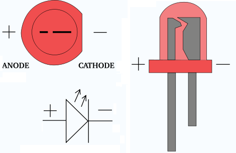
Firstly be aware that a LED is a diode, meaning that it is polarized. By convention, current can only go from the anode (positive end) to the cathode (ground, or negative end).

How do you know which end is which? Note that the two wires on the LED are different lengths. The longer wire is always + and the shorter is -.

There are other ways to tell which lead is which. If you look from the top down, you will notice one side has a flat edge. That edge is ground. If you look inside, you can even tell by the shapes you see.


LEDs are specially constructed to release a large number of photons outward. Additionally, they are housed in a plastic bulb that concentrates the light in a particular direction. As you can see in the diagram, most of the light from the diode bounces off the sides of the bulb, traveling on through the rounded end.


LEDs have several advantages over conventional incandescent lamps.LEDs can have lifetimes of 50,000 hours or more.Owing to their size and packing they are lot more durable and fit more easily into modern electronic circuits.

But the main advantage is efficiency. In conventional incandescent bulbs, the energy is vastly consumed in heat (filament is heated). This is completely wasted energy, unless you're using the lamp as a heater, as a huge portion of the available electricity isn't going toward producing visible light.

On the other hand almighty LED generate very little heat and high vibrant light. A much higher percentage of the electrical power is going directly to generating light, which cuts down on the electricity demands considerably.

Early LEDs were often used as indicator lamps for electronic devices, replacing small incandescent bulbs. They were soon packaged into numeric readouts in the form of seven-segment displays, and were commonly seen in digital clocks.


Light-emitting diodes are now used in applications as diverse as aviation lighting, automotive headlamps, advertising, general lighting, traffic signals, and camera flashes.


 However, LEDs powerful enough for room lighting are still relatively expensive, and require more precise current and heat management than compact fluorescent lamp sources of comparable output.


LED chips need controlled direct current (DC) electrical power; an appropriate circuit is required to convert alternating current from the supply to the regulated low voltage direct current used by the LEDs. LEDs are adversely affected by high temperature, so LED lamps typically include heat dissipation elements such as heat sinks and cooling fins.


For more info and cool DIY, visit these sites :


Saturday, May 9, 2015

Path Following Bot


Path follower Bot is another version of a Line Follower Robot. It consists of two major components:


(1) Hardware ( includes the sensors and driving mechanisms ) (2) Software ( path following and grid solving algorithm coded into microcontroller )

Let’s look at the hardware side of the bot : The hardware of the Path follower Bot plays a vital role in functionality of the robot. It should be designed for providing accurate information to the “brain” of the Path follower bot and should be efficient in executing the decisions made by it. The hardware includes:


 Sensor 


Sensors used in Path follower bot are Infrared sensors for the purpose of path following and to determine the obstructions in the course. An IR sensor uses the same principle but uses Infrared LEDs instead of ordinary LEDs. Both IR and LDRs can be used for line following, but it would be better to use an IR sensor for determining the obstruction ahead.


Working principle of the IR sensors :


Infrared sensors detect infrared light. The IR light is transformed into an electric current, and this is detected by a voltage or amperage detector. A property of light-emitting diodes (LEDs) is that they produce a certain wavelength of light when an electric current is applied--but they also produce a current when they are subjected to the same wavelength light.

A pair of IR LEDs can be used as motion detectors.

IR sensor is wired in such a way that first IR LED is wired to transmit IR light which is not visible to human eyes. The second LED which is IR detector is basically an IR transistor, due to object ahead IR light from IR LED is reflected back to IR detector, this in turn makes IR transistor to generate a signal. This signal can be amplify depending upon the need.

The signal thereby can be used to drive motor, buzzer, or as an information to microcontroller.


Gear motor


A geared motor is basically a DC motor coupled with gear box, this is done to get high RPM and Low torque OR low RPM and high torque.

Any geared motor can be used to drive a bot. But one should ensure that the motor is not too fast that the sensors don’t get sufficient time to sense the path’s edges. Direct connection of motor with the microcontroller is not possible. So for ordinary geared motors a motor driving IC L293D must be used. It has got many other functions such as enabling differential drive (mobility in all direction) and pulse width modulation for controlling the speed of motor.


Microcontroller


Microcontrollers are programmable ICs in which you can store a program in machine code and
execute it. There are many micro controllers but use of either ATmega 16 or ATmega 32 will be
sufficient for solving the path follower or line follower.

ATmega 16 and ATmega 32 are basically same in pin diagram and function except the fact that ATmega 32 has more programmable memory.

ATmega 16 has 4 ports and each port having eight pins. A port is place where you can give your input

(sensors) and tap outputs (motors) depending upon the way they are defined in the program (code)

you load into the micro controller.

There are plenty of AVR board in online stores which are having Atmega16/32 mcu onboard and motor driver IC for driving DC motor and sensor input connection.

These plug n play AVR boards comes with programmer cable as well, through which anyone having programming skill can program these boards and can make such robots on such platform.

Also there are freeduino boards which are easy to program and wired to make line following robot.


Algorithm


Some basic and advance line following tutorials can be found here :
Take a look on this video, how the four sensor based path follower robot is actually showing its skills..

 https://www.youtube.com/watch?feature=player_embedded&v=e1k-RzQ4PTI